|
|
Post by twistedindustries on Jun 10, 2018 1:36:17 GMT -5
I am swapping my 1990 ranger and the donor car is 1984 capri with a LA3 ECU. I've got a couple questions after following the 91-93 guide as suggested in previous searches.
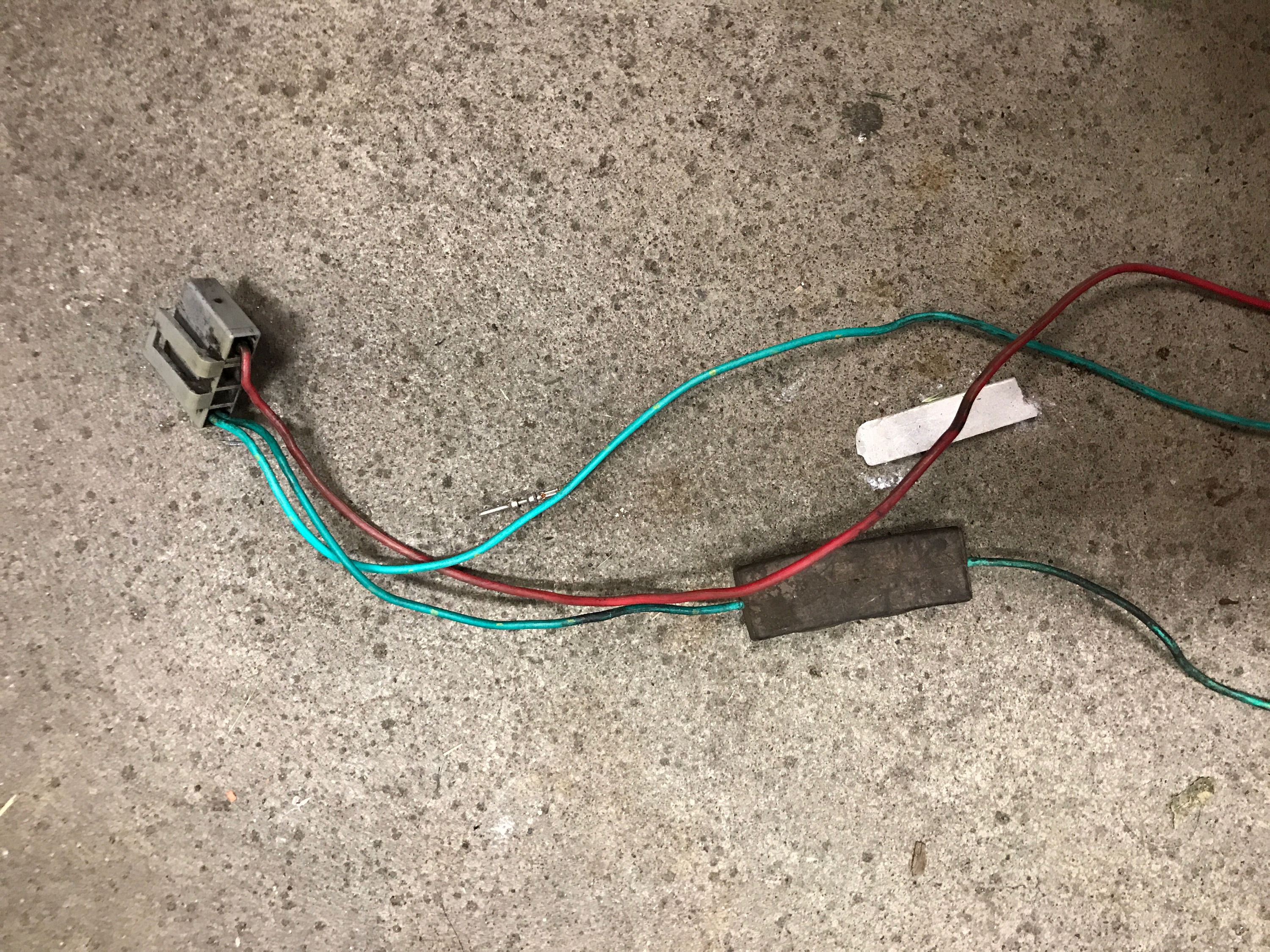
Pin 12, now pin 5, of the ICM is supposed to go to pin 4 of the ECM but mine goes to pin 7 on the instrument cluster. Pin 4 of the ECM actually goes to pin 6 of the instrument cluster as shown here:http://www.therangerstation.com/tech_library/EDiagrams/files/Diagram_Ignitionsystem_1990_2_3.JPG I realize it shows there is a splice connecting the two wires [S126] but I can't seem to verify this with a multimeter anywhere. So I am not sure exactly how to connect my coil [harness pictured below], my coil has two green wires, and one red wire. One green wire has something inline and seems to be a "resistor in-line diode" as described on page 4 of this pdf: www.mc-machine.com/pdf/1984.pdf. Testing on each side of the "resistor in-line diode" with a multimeter I get no continuity.
How should I hook up the coil wires, I am thinking that the wire with the "resistor in-line diode" should go to the wire that goes directly to pin 4 of the ECM [and pin 6 of the cluster] and the wire with nothing inline should go to pin 5 [previously pin 12] of the ICM, does that seem right?
Ignition coil wire harness:
Edit: Added what ecu is being used.
|
|
|
|
Post by Stinger on Jun 10, 2018 17:38:57 GMT -5
I don't know what the cluster has to do with anything. It's never once mentioned in the swap guide since none of that is modified, cut, or moved at all. The coil wiring is self contained between the TFI and coil. You just tap into it right at the TFI and leave the rest of the stock wiring alone and the tach, TFI, and coil will work.
|
|
|
|
Post by twistedindustries on Jun 10, 2018 21:42:03 GMT -5
Thanks for the reply, what has me confused is that the guide specifically says that pin 5 at the TFI should go to pin 4 of the ecm but mine doesn't.
I'll just tap that wire as you said but that leaves the question, which green wire do I use? The one with the brick or the one without? Should I just leave the other wire unhooked?
Again, thanks for your time.
|
|
|
|
Post by Stinger on Jun 11, 2018 9:07:18 GMT -5
|
|
|
|
Post by twistedindustries on Jun 11, 2018 10:53:16 GMT -5
Ok, mine just isn't wired that way for some reason.
I see the noise capacitor in your diagram, it's wired to the pos side of the coil. Mine is on the neg side of the coil.
|
|
|
|
Post by Stinger on Jun 11, 2018 13:09:21 GMT -5
I don't think it matters which side it's on in order to do it's job. I think the diagram may be inaccurate in that regard though as the resistor is on the IDM/pin 4 wire in stock form.
|
|
|
|
Post by twistedindustries on Jun 11, 2018 13:50:02 GMT -5
Thanks for your help, I'll report back when I get it going which is hopefully soon
|
|
|
|
Post by twistedindustries on Jun 28, 2018 18:51:46 GMT -5
Just wanted to report back. The block in the ground wire turned out to be a 22k ohm resistor. Mine was bad, so I replaced it with a new one. That ended up getting connected to the wire that goes to pin 4 on the ecu which wasn't the wire on the ignition module. The other ground wire got connected to the tach wire which was the wire coming from the ignition module.
|
|